Live register. One record ingested from live sources at a time; the register populates from the daily EPO OPS sweep.

Prior art register

Have you seen this built before?

Prior art is public proof — a product, a method, a paper — that an idea existed before a patent’s priority date. It can narrow or kill that patent. Electronics, pharma, and software have run prior art registers for decades. Industrialised construction never has. This is the first.

Every patent filed in the modular and prefabricated building classes lands here automatically, claims exactly as published. Seen a method in use before its priority date? Tell us. No human picks what appears here, and nothing here is a ruling on validity.

Open to observations
Not granted yet — file prior art with the examiner now, free and anonymous.
Open to opposition
Granted, within 9 months — a formal opposition (fee) can revoke or narrow it.
Status unconfirmed
Register position not resolved yet — tell us anyway and we’ll hold it.
Window closed
Opposition period passed — no EPO route left, but it still counts for the record.
255 records ingested·Classes E04B1/00, E04B1/343, E04B1/348, E04H1/00, E04H1/12
WO 2 026 057 296 A1

OMANADZE EMMA · IT

Open to opposition

A PANEL KIT FOR PANEL BUILDING ON-SITE ASSEMBLY

Evidence must predate13 Sept 2024
Claim 1, exactly as publishedretrieved
A kit of a high factory readiness panels for a panel building construction, comprising the following panels with connectors and a joint: a wall panel (1), a corner panel (7), a ceiling panel (31), a floor panel (20) and a roof (37), wherein the wall panel (1) having an interior face (2) and an exterior face (3), spaced apart from the interior face (2), two side edges (4), where each side edge (4) extends between the interior face (2) and the exterior face (3) throughout the entire height of the wall panel (1), and a top edge (5) and a bottom edge (6), wherein the comer panel (7) having two parts indivisibly joint at a right angle forming a comer of the corner panel, each part has an interior face (8) and an exterior face (9), spaced apart from the interior face (8), side edges (10) faced away from the corner of the comer panel (7), where the side edges (10) extend between the interior face (8) and the exterior face (9) throughout the entire height of each part of the comer panel (7), and a top edge (11) and a bottom edge (12), wherein the width of the side edge (4) of the wall panel (1) corresponds with a width of the side edge (10) of the corner panel (7), wherein the ceiling panel (31) having an upper side (32) and a lower side (33), and four side edges (34), each of the side edges (34) comprises a protrusion (36) arranged close to an upper side of the ceiling panel (32) and a corresponding L-type recess (35) arranged close to a lower side of a ceiling panel (33) facing in a direction towards the lower side (32) of the ceiling panel (31), wherein the floor panel (20) having a frame (21) along the perimeter of the floor panel (20), wherein the frame (21) having a recess (22) extending along the perimeter of the frame (21), and a H-type connector (23) on each side of the panel (20) directed towards an interior of the building for interjunction of multiple floor panels (20), wherein the bottom edge (6, 12) of the wall panel (1) and of the corner panel (7) comprises a T-type connector (13) extending along the entire length of the bottom edge (6, 12) of the same in the longitudinal direction, wherein the top edge (5, 11) of the wall panel (1) and of the comer panel (7) comprises a Il-type connector (15) extending along the entire length of the top edge (5, 11) of the same in the longitudinal direction, wherein each side edge (4, 10) of the wall panel (1) and the comer panel (7) having a vertically aligned groove (19), that is narrow at the outermost part of the side edge (4, 10) of the wall panel (1) and the comer panel (7), and becomes progressively wider as it goes deeper into a body of the panel (1, 7), wherein the Il-type connector (15) is defined by an angular protrusion (16) having a vertical section (17) and a horizontal arm (18) connected under a right angle, wherein the protrusion (36) of the ceiling panel (31) is formed so that upon assembly of the wall panel (1) and the corner panel (7) with the ceiling panel (31), the protrusion (36) of the ceiling panel (31) is received in the angular protrusion (16) of the Il-type connector (15) of the wall panel (1) and the corner panel (7) so that the interference fit is formed between the panels (1, 7, 31), wherein the protrusion (14) of the T-type connector (13) of the wall panel (1) and the corner panel (7) is formed so that upon assembly of the wall panel (1) and the comer panel (7) with the floor panel (20) the protrusion (14) of the T-type connector (13) of the wall panel (1) and the comer panel (7) is received in the recess (22) of the floor panel (20) so that the interference fit is formed between the panels (1, 7, 20), wherein a roof (37) having a frame (37), said frame (8) comprises a L-type lip (39) extending downwards and faces the top edge (5, 11) of the wall panel (1) and the corner panel (7), so that the interference fit is formed between the panels (1, 7, 37), the kit further comprises a E-type joint (23) in a form of an elongated beam (29) having four side faces (27), a top edge (25), and a bottom edge (26), wherein the joint (23) on each of its side faces (27) comprises a protrusion (28) so that upon assembly of multiple wall panels (1) and comer panels (7) the protrusion (28) forms an interference fit with the groove (19) of the same, wherein the beam (29) of the X-type joint (23) corresponds with a width of the wall panel (1) and the corner panel (7)
Plain English, unofficialA kit of prefabricated building panels is described, comprising wall panels, corner panels (each formed of two parts joined at a right angle), ceiling panels, floor panels, and a roof, together with connectors and a joint element for assembling them. Wall and corner panels have matching side edge widths and include a T-type connector along their bottom edge, a Il-type connector along their top edge, and a vertically tapering side groove; the ceiling panel has edge protrusions and L-type recesses that engage the Il-type connector by interference fit, the floor panel has a perimeter frame with a recess engaging the T-type connector's protrus
Priority13 Sept 2024
Published19 Mar 2026 (A1)
InventorsOMANADZE EMMA
Family members2 grouped
E04B1/02E04B1/34321E04B1/6162E04B2001/6195
EP 1 967 043 B1

EXATEC LLC · US

Open to observations

APPARATUS AND METHOD OF DISPENSING CONDUCTIVE MATERIAL WITH ACTIVE Z-AXIS CONTROL

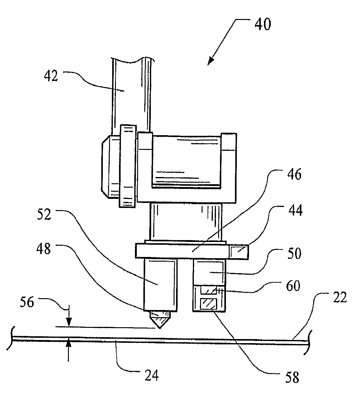
Front-page drawing from EP 1 967 043 B1
Evidence must predate29 Dec 2005
Claim 1, exactly as publishedretrieved
Vorrichtung (40) zum Drucken einer leitfähigen Tinte auf eine Kunststofftafel (24), wobei die Vorrichtung (40) Folgendes umfasst: einen Träger (38), der beschaffen ist, um die Tafel (24) zu stützen; ein abwinkelbares Element (42), das bezüglich des Trägers (38) so positioniert ist, dass ein Ende des Elements (42) einer Oberfläche (22) der zu bedruckenden Tafel (24) gegenüberliegt; eine Düse (48), die durch das Element (42) getragen ist und an dem Ende an ihm angebracht ist, wobei die Düse (48) an eine Quelle (49) der leitfähigen Tinte gekoppelt ist; einen Düsenhöhen-Aktuator (52), um die Düse (48) entlang einer z-Achse bezüglich der Oberfläche (22) der Tafel (24) zu heben und zu senken; einen Durchflussmengenregulierer (47), der an die Tintenquelle (49) und an die Düse (48) gekoppelt ist, wobei die Durchflussmenge der leitfähigen Tinte aus der Düse (48) durch den Durchflussmengenregulierer (47) reguliert wird; einen Höhensensor (50); und eine Steuereinrichtung (45), die an das Element (42), den Durchflussmengenregulierer (47), den Düsenhöhen-Aktuator (52) und den Höhensensor (50) gekoppelt ist, wobei die Steuereinrichtung (45) konfiguriert ist, um das Abwinkeln des Elements (42) zu veranlassen, um die Düse (48) in einem vorgegebenen Muster über die Oberfläche (22) der Tafel (24) zu bewegen, dadurch gekennzeichnet, dass der Düsenhöhen-Aktuator (52) durch das Element (42) getragen ist und die Düse (48) an dem Element (42) anbringt; der Höhensensor (50) konfiguriert ist, um den Abstand der Düse (48) von der Oberfläche (22) der Tafel (24) zu messen und das Höhensignal bezüglich der Oberfläche (22) der Tafel (24) auszugeben; und die Steuereinrichtung konfiguriert ist, um den Durchflussmengenregulierer (47) und/oder den Düsenhöhen-Aktuator (52) zu steuern, wie das Element (42) jeweils als eine Funktion der Geschwindigkeit, mit der die Düse (48) bewegt wird, und/oder einem Höhensignal von dem Höhensensor (50) und/oder der Durchflussmenge der leitfähigen Tinte aus der Düse (48) abgewinkelt wird, so dass eine leitfähige Spur mit einer vorgegebenen Höhe und Breite auf die Tafel (24) aufgebracht wird
Plain English, unofficialA device for printing conductive ink onto a plastic panel is described, comprising a carrier supporting the panel, a bendable element positioned so one end faces the panel surface, a nozzle mounted at that end and coupled to a conductive ink source, a nozzle-height actuator carried by the bendable element for raising/lowering the nozzle along a z-axis, a flow-rate regulator coupling the ink source to the nozzle, a height sensor measuring nozzle-to-surface distance and outputting a corresponding signal, and a controller coupled to the element, flow-rate regulator, actuator, and height sensor. The
Priority29 Dec 2005
Published1 Feb 2012 (B1)
InventorsSCHWENKE ROBERT, VAN DER MUELEN ERIC, BUI BILLY, WEISS KEITH
Family members10 grouped
B05C5/00B05C5/0225E04B1/00H05B3/86H05B2203/017
EP 2 052 169 B1

FIKE CORP · US

Open to observations

SEAL FOR SANITARY OVERPRESSURE VENT STRUCTURE

Evidence must predate17 Aug 2006
Claim 1, exactly as publishedretrieved
Dichtung (16) für eine Sanitär-Überdruckentlastungsvorrichtung (10) mit einer Rahmenstruktur (12), die gegenüberliegende Flächen hat, zwischen denen der Umfangsbereich einer Entlüftungsmembraneinheit (14) aufgenommen ist, wobei die Entlüftungsmembraneinheit (14) benachbart zur Rahmenstruktur (12) mit einer Reihe von Schlitzen (28) versehen ist, wodurch ein Entlastungsgebiet (30) der Entlüftungsmembraneinheit (14) gebildet ist, wobei die Dichtung (16) ausgestaltet ist, um in dichtender Beziehung zwischen der Entlüftungsmembraneinheit (14) und einer der Rahmenstrukturflächen angeordnet zu sein, dadurch gekennzeichnet, dass die Dichtung (16) aufweist: einen länglichen, flexiblen, einteiligen Körper (38) mit einem zentralen Abschnitt (40), der ausgestaltet ist, um im Wesentlichen mit den eine Schwächungslinie definierenden Schlitzen (28) in der Entlüftungsmembraneinheit (14) ausgerichtet zu sein, wenn die Dichtung (16) zwischen der Entlüftungsmembraneinheit (14) und der einen Rahmenstrukturfläche montiert ist, einen Haupt-Rippenbereich (46), der mit dem zentralen Abschnitt (40) des Dichtungskörpers (38) einstückig ist und davon in eine Richtung vorsteht, um dichtend mit der Entlüftungsmembraneinheit (14) einzugreifen, und zwar nach innen gerichtet von der Schwächungslinie bezüglich der Rahmenstruktur (12), ein Sekundär-Rippensegment (48), das mit dem zentralen Abschnitt (40) des Dichtungskörpers (38) einstückig ist, von dem Haupt-Rippenbereich (46) beabstandet ist, und sich außenliegend zum Haupt-Rippenbereich (46) sowie innenliegend zu den die Schwächungslinie definierenden Schlitzen (28) in einer Position zu befinden, um in der montierten Position der Dichtung (16) mit der Entlüftungsmembraneinheit (14) einzugreifen, wobei eine längliche, sich in Längsrichtung erstreckende Kavität (50) in dem zentralen Abschnitt (40) des Dichtungskörpers (38) zwischen dem Haupt-Rippenbereich (46) und dem Sekundär-Rippensegment (48) in einer der Entlüftungsmembraneinheit (14) zugewandten Beziehung vorgesehen ist, wobei der Haupt-Rippenbereich (46) und das Sekundär-Rippensegment (48) jeweils relative Längen haben und in Positionen angeordnet sind, so dass der Haupt-Rippenbereich (46) und das Sekundär-Rippensegment (48) relativ in entgegengesetzte Richtungen aufeinander zu und voneinander weg bewegbar sind, wobei der eng abdichtende Kontakt mit der Entlüftungsmembraneinheit (14) in der montierten Position der Dichtung (16) beibehalten wird, wenn sich die Entlüftungsmembraneinheit (14) während der Verwendung der Vorrichtung (10) rein- und rausbewegt
Plain English, unofficialA seal for a sanitary pressure-relief device is described, positioned in sealing relation between a vent diaphragm unit and a frame structure face, where the diaphragm unit has slots near the frame forming a relief area along a weakening line. The seal has an elongated, flexible, one-piece body with a central section aligned with the slots, a main rib portion projecting inward of the weakening line to engage the diaphragm, a secondary rib segment spaced from and outside the main rib but inside the slots to also engage the diaphragm, and an elongated longitudinal cavity between the two ribs facing the diaphragm, with the main
Priority17 Aug 2006
Published20 Mar 2013 (B1)
InventorsEIJKELENBERG TOM
Family members25 grouped
E04B1/00E04H9/00F16J15/025F16J15/06F16J15/064F16J15/067F16J15/46F16K17/0453F16K24/04
EP 2 367 926 B1

X TU · FR

Open to observations

DEVICE FOR CULTIVATING ALGAE AND/OR MICROORGANISMS FOR TREATING AN EFFLUENT, AND BIOLOGICAL FRONTAGE

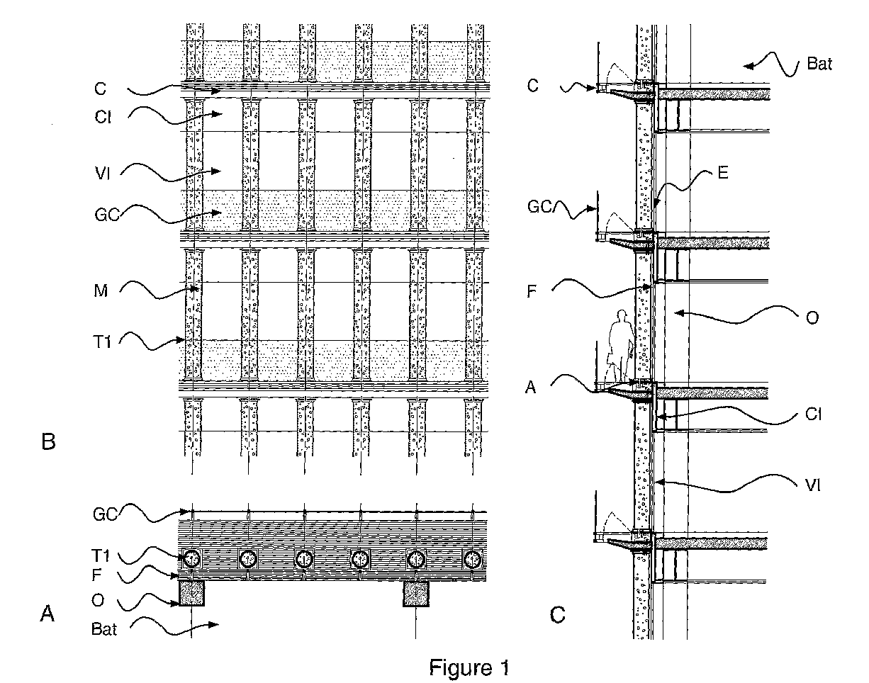
Front-page drawing from EP 2 367 926 B1
Evidence must predate23 Dec 2008
Claim 1, exactly as publishedretrieved
Verwendung einer Vorrichtung zur Behandlung von Abflüssen und/oder zur Herstellung einer Biomasse umfassend: - einen Behälter für die Kultur von Algen und/oder Mikroorganismen in einem wässrigen Medium, - ein Mittel zum Nähren der Algen- und/oder der Mikroorganismenkultur, - ein Mittel zum Einspritzen von Abflüssen in die Algen- und/oder Mikroorganismenkultur, wobei die Abflüsse von einem Gebäude stammen, - ein Mittel zur Regulierung der Temperatur der Algen- und/oder Mikroorganismenkultur, - gegebenenfalls eine der Algen- und/oder Mikroorganismenkultur förderliche Beleuchtung, und - ein Mittel zur Rückgewinnung der Abflüsse, das es ermöglicht, die Abflüsse eines Gebäudes zu sammeln, um sie in die Algen- und/oder Mikroorganismenkultur einzuspritzen, in welcher der Behälter für die Algen- und/oder Mikroorganismenkultur zwischen zwei Oberflächen angebracht ist: eine Gebäudeoberfläche und eine Außenoberfläche, die eine zweite Haut bildet, und wobei die Abflüsse von dem Gebäude mit der doppelten Haut und/oder von einem anderen Gebäude kommen
Plain English, unofficialThe claim covers the use of a device for treating drainage water and/or producing biomass, comprising a container for culturing algae and/or microorganisms in an aqueous medium, a feeding means for the culture, an injection means for introducing drainage water from a building into the culture, a temperature-regulation means, optionally lighting to promote the culture, and a recovery means for collecting the building's drainage water for injection into the culture, where the culture container is positioned between a building surface and an outer surface forming a second skin. The drainage water used may originate from the double-skin building itself and/or from another building.
Priority23 Dec 2008
Published6 Mar 2013 (B1)
InventorsLEGENDRE ANOUK, DESMAZIERES NICOLAS
Family members11 grouped
C02F3/00C12M1/38C12M21/02C12M23/00C12M3/02E04B1/00E04B1/74E04B1/92Y02W10/30Y02W10/37
EP 2 261 430 A2

HAEMEEN TERAESRAKENNE OY · FI

Open to observations

Constructing an overhang

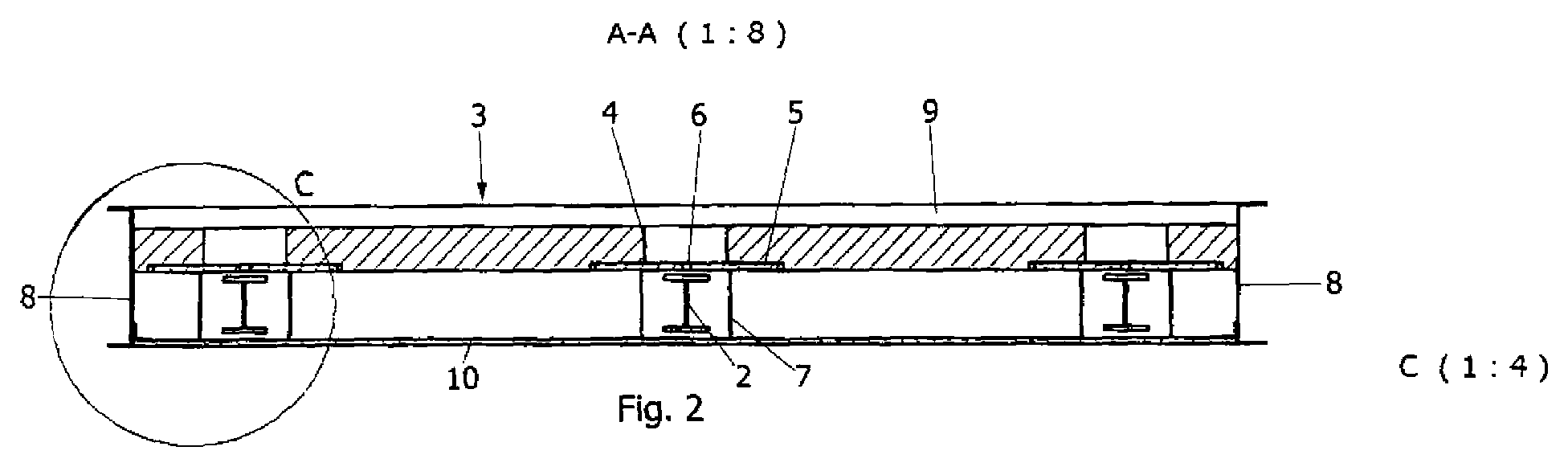
Front-page drawing from EP 2 261 430 A2
Evidence must predate10 Jun 2009
Claim 1, exactly as publishedretrieved
A method for constructing a concrete overhang on the wall of a building, said method comprising arranging the overhang to be supported upon wall-mounted cantilever beams (2), characterized in that - a concrete slab (3) is cast and its bottom surface is formed with an enclosure (7), which is in line with each beam (2) and within which the beam settles as the slab is placed to be supported upon the beams, - the slab is placed upon the beams for support, and - the slab is secured to the beams
Plain English, unofficialThe claim describes a method of building a concrete overhang on a wall by supporting it on cantilever beams mounted to the wall, where a concrete slab is cast with an enclosure formed in its bottom surface aligned with each beam so that the beam fits into the enclosure when the slab is set in place. The slab is then placed onto the beams for support and secured to them.
Priority10 Jun 2009
Published15 Dec 2010 (A2)
InventorsKARIMIES MARTTI
Family members5 grouped
E04B1/00E04B1/003E04B1/38E04C2/04
EP 2 646 390 B1

CEMEX RES GROUP AG · CH

Open to observations

REINFORCED WALL SYSTEM AND METHOD

Evidence must predate2 Dec 2010
Claim 1, exactly as publishedretrieved
Verfahren zum Bau eines Bauwerks zur Erfüllung einer geltenden Bauordnung, wobei das Verfahren folgende Schritte umfasst: Setzen einer Betonform, welche eine Kavität aufweist, an der Stelle, an welcher das Bauwerk gebaut werden soll; Setzen einer begrenzten Menge an Metallverstärkungen innerhalb der Kavität, so dass die begrenzte Menge an Metallverstärkungen nicht ausreicht, um die anwendbare Bauordnung zu erfüllen; Einfüllen einer Mischung aus zwischen 40 und 50 % Stein, zwischen 30 und 40 % Sand, zwischen 10 und 15 % Portlandzement, zwischen 5 und 10 % Flugasche, zwischen 0,5 und 2 % Mineralfasern einschließlich Calciumsilikat (CaSiO<3> ) -fasern oder Mineralfasern einschließlich eines oder mehrerer Minerale der Pyroxengruppe von Mineralen und zwischen 0,005 und 5 Gewichts-% an Zusätzen in die Kavität; und Aushärtenlassen der Mischung, womit die geltende Bauordnung ohne eine zusätzliche Metallverstärkung erfüllt wird
Plain English, unofficialA method for constructing a building structure to satisfy an applicable building code, comprising placing a concrete form with a cavity at the construction site, placing within the cavity a limited quantity of metal reinforcement insufficient by itself to meet the applicable building code, filling the cavity with a mixture of 40–50% stone, 30–40% sand, 10–15% Portland cement, 5–10% fly ash, 0.5–2% mineral fibers (including calcium silicate fibers or mineral fibers containing one or more pyroxene group minerals), and 0.005–5 wt% additives, and allowing the mixture to c
Priority2 Dec 2010
Published7 Jan 2015 (B1)
InventorsGOERGER BRYAN, ORTIZ MARCELO, UZCATEGUI FRANCISCO, THIEL PATRICK
Family members12 grouped
C04B28/04E04B1/00E04B2/86Y02W30/91

Sign in to see all 255 records in the register.

Sign in